TinyPico & MicroPython !

Received my TinyPico boards I backed on Crowd Supply, and making some notes based on Seon’s Youtube video “MicroPython #1 – Lets Get Started”.

Download from: http://micropython.org/download#esp32

Using OSX, Terminal

ls /dev/tty.*

/dev/tty.SLAB_USBtoUART
esptool.py --chip esp32 --port /dev/tty.SLAB_USBtoUART erase_flash
esptool.py --chip esp32 --port /dev/tty.SLAB_USBtoUART --baud 460800 write_flash -z 0x1000 esp32-20190731-v1.11-182-g7c15e50eb.bin
screen /dev/tty.SLAB_USBtoUART 115200

Gives a python prompt from the TinyPico !

https://github.com/dhylands/rshell

sudo pip3 install rshell
rshell -p /dev/tty.SLAB_USBtoUART 
ls /pyboard

cp micropython_dotstar.py /pyboard
repl
import example.py


Posted in Uncategorized | Leave a comment

MAX7219 Clock countdown for artworks


Using a pre-loved Telechron 6-digit 7-segment clock, controlled by a MAX7219 IC…


On power up.. clock to display  00 00 00

if Digital I/O xx is HIGH (pulled to 5v) (requires external pull-up-resistor)

counter = 1 hour.  ** Closed contact closed, or button pushed..

Counter is always counting down

When clock gets to 00 00 00, stop counting.


Closed contact from Brightsign Relay box, when clip starts – timecode 00h00m00s00f  for 2 seconds.. tells clock to start counting down.


Code: https://github.com/dargs/timer


Parts:

1x ATMega168

1x 16MHZ Crystal

2x 22pF Caps

10k resistor (reset pullup)

10uF cap (decoupling)


Posted in Uncategorized | Leave a comment

Teensy Hardware Joystick & Keyboard emulator

Testing if Teensy can be a Joystick and a Keyboard.. as some game emulators expect joystick commands as default, but require keyboard keys also. Handy in installation environment.


/* Basic USB Joystick Example

  GPIO 0 Keyboard - F1
  GPIO 1 Keyboard - F3
  GPIO 2 Keyboard - F5
  GPIO 3 Joystick -X
  GPIO 4 Joystick +X
  GPIO 5 Joystick -Y
  GPIO 6 Joystick +Y
  GPIO 7 Joystick Button 1 FIRE

Set Teensy 3.2 to be Serial/Joystick/Host.
*/

#include <Bounce.h>

// Create Bounce objects for each button.  The Bounce object
// automatically deals with contact chatter or "bounce", and
// it makes detecting changes very simple.

Bounce button0 = Bounce(0, 10);  // F1
Bounce button1 = Bounce(1, 10);  // F3 10 = 10 ms debounce time
Bounce button2 = Bounce(2, 10);  // F5  which is appropriate for

int ledPin = 13;
const int joystick_X_neg_pin = 3;
const int joystick_X_pos_pin = 4;
const int joystick_Y_neg_pin = 5;
const int joystick_Y_pos_pin = 6;
const int joystick_fire_pin = 7; 

void setup() {
  pinMode(0, INPUT_PULLUP);
  pinMode(1, INPUT_PULLUP);
  pinMode(2, INPUT_PULLUP);
  pinMode(3, INPUT_PULLUP);
  pinMode(4, INPUT_PULLUP);
  pinMode(5, INPUT_PULLUP);
  pinMode(6, INPUT_PULLUP);  // Teensy++ LED, may need 1k resistor pullup
  pinMode(7, INPUT_PULLUP);
  pinMode(ledPin, OUTPUT);     

  Serial.begin(9600);
  Serial.println("... Setup ... ");
}

void loop() {
 
  // Update all the buttons for the keyboard.  There should not be any long
  // delays in loop(), so this runs repetitively at a rate
  // faster than the buttons could be pressed and released.

  button0.update(); // F1 Start
  button1.update(); // F3 1/2 Player
  button2.update(); // F5 Restart

// Check each button for "falling" edge.

  if (button0.fallingEdge()) {
    Keyboard.press(KEY_F1); // Button 0 = F1 = Start Game
    delay(10);
    Keyboard.release(KEY_F1);
  }

  if (button1.fallingEdge()) {
    Keyboard.press(KEY_F3); // Button 1 = F3 = 1 Player / 2 Player
    delay(10);
    Keyboard.release(KEY_F3);
  }
 
  if (button2.fallingEdge()) {
    Keyboard.press(KEY_F5); // Button 2 = F5 = Restart Game
    delay(10);
    Keyboard.release(KEY_F5);    
  }

if (digitalRead(joystick_X_neg_pin) == LOW)
    {    
    Joystick.X(0);          // Min X
    } else if (digitalRead(joystick_X_pos_pin) == LOW)
    {
    Joystick.X(1023);          // Max X
    } else   {
    Joystick.X(512);          // X Centred
   }

if (digitalRead(joystick_Y_neg_pin) == LOW)
   {
    Joystick.Y(1023);          // Y Max
  } else if (digitalRead(joystick_Y_pos_pin) == LOW)
    {
    Joystick.Y(0);          // Y Min
  } else {
    Joystick.Y(512);          // Y Centred
  }

if (digitalRead(joystick_fire_pin) == LOW) {
    Joystick.button(1, HIGH);  // Button  1 = FIRE High
    delay(10);
  } else {
    Joystick.button(1, LOW);  // Button  1 = FIRE Low
  }

  delay(50);  // a brief delay
}
Posted in Arduino-Projects, electronics | Tagged , , , | Leave a comment

USB Remote monitor

Web enabled (ESP32 ? PoE Shield ?)

USB Tester OLED

https://www.tindie.com/products/FriedCircuits/usb-tester-20-bundle/

https://github.com/FriedCircuits/FC-USB-Tester-OLED-Backpack/blob/master/USB_Tester_v1/Pre_JSON/USB_Tester_OLED/USB_Tester_OLED.ino


Monitors Voltage and Current for installations (Keyboards, Mice, Game Controllers). Able to report via web interface / SNMP under voltage / disconnects


Posted in Uncategorized | Leave a comment

RS232 Serial debugger


Passive split: (No latency, no re-transmitting packets…. Receive Only, can’t tell which device is sending)

https://www.compuphase.com/electronics/rs232split.htm

.. Use 2 splits, into 2 MAX232s into 2 Serial RX on Teensy.


Serial In (From Control System)

MAX232 -> TTL Serial #1

Microcontroller (Teensy?)  Echos incoming strings to output, and onto – USB for Monitoring & Manual commands on local laptop running Putty etc.

TTL Serial #2 -> MAX232

Serial Out (To Device under test – ie Projector)


  • USB control includes prompt to change baud rate. Settings stored to EEPROM.
  • Phoenix to Screw terminals TX/RX/GND
  • Phoenix to DB9 connector adapter.
  • Phoenix to RJ45 adapter
  • jumpers to bypass TX / RX
  • LEDs to indicate traffic on bus.


Optional

  • Ethernet to remotely log
  • SD Card slot to log inc Real Time Clock.
  • LCD / OLED for local monitoring
Posted in electronics, Uncategorized | Tagged | Leave a comment

Brightsign media player Relay & Button control PCB

DB15 IDC Connector

https://www.digikey.com.au/product-detail/en/cnc-tech/410M0-15-1-00/1175-1813-ND/6024195


15cm 16 way ribbon cable

https://www.digikey.com.au/product-detail/en/assmann-wsw-components/AWG28-16-G-300/AE16G-5-ND/686332


16 Pin 8×2 Header

https://www.digikey.com.au/product-detail/en/on-shore-technology-inc/302-S161/ED10523-ND/2794234


Jumper select ? for Relay vs Button (GPI vs GPO) or have 4 relays, 4 buttons?

3 way Screw Terminals (Relays C, N/C, N/O) x 4

2 way Screw Terminals x 4 (Buttons)

9v ? 5v ? 500mA DC Input (5v Relays)

https://www.digikey.com.au/product-detail/en/omron-electronics-inc-emc-div/G5LE-1-ASI-DC5/Z5212-ND/414237


Transistors x4

Diodes x 4

Resistors

LEDs PSU

LED Off/On per channel?

PCB

DIN Rail enclosure


Posted in electronics | Leave a comment

Prey Q&A with Raphael Colantonio

https://www.acmi.net.au/events/prey-raphael-colantonio/

Posted in Uncategorized | Leave a comment

VDMX PIR Looping vid control trigger

Debug:

LED ON = Digital pins pulled high (internal pullup) = Motion Sensed (Or Faulty PIR / Wiring)


/* PIR Motion Sensor to MIDI Trigger w timer
 25/3/2017 Dargstronix

 Hardware: 
 1x PIR Sensor (4 pins to sensor = 12v, GND, 2x alarm pins) * Could add more sensors for increased responsiveness to movement)
 1x 12v 500mA PSU for PIR 
 PIR Alarm Pins to Teensy GND / Pin 0 
 1x Teensy v3.5 (5v version) - Set USB Type to MIDI + Serial * Powered by USB (mac pro)
 
 Compiled under Arduino v 1.6.13 https://www.arduino.cc/en/Main/OldSoftwareReleases#previous
 Teensyduino 1.35 https://www.pjrc.com/teensy/td_download.html
 VDMX Detect MIDI on Video Layer (Default CC 11)
 
*/

int pirPin = 0; // Pin for PIR (Normally Closed)
int ledPin = 13; // Built in LED (default pin 13) NO Hardware PWM on Pin 13.
long counter = 0; // counter
long video = 0; // value to store state of if video should play or not.
int ledState = LOW; // ledState used to set the LED
long previousMillis = 0; // will store last time LED was updated
unsigned long currentMillis = millis();


/* User Config */

long duration = 5000; // Time to wait before turning up idle video loop (in mS) 5000 = 5 seconds, 60000 = 60seconds
int fadetime = 20; // fade up/down time in mS ( x 128 ) = 2.5 seconds
int midich = 0; // MIDI Channel: 0 is default
int midicc = 11; // MIDI Control Channel: 11 (MIDI CC Volume) is default 


void setup() 
{
 pinMode(pirPin, INPUT_PULLUP); // internal pullup to HIGH
 pinMode(ledPin, OUTPUT);
 Serial.begin(9600); // debug
}


void loop() 
{
 currentMillis = millis();
 int pirState = digitalRead(pirPin);
 Serial.print(" pirState: "); //debug
 Serial.print(pirState); //debug

if (pirState == HIGH) // If PIR triggered
 { 
 digitalWrite(ledPin, HIGH);

 if (video==1)// If video was playing, then make it not play
 { 
 Serial.println(" *** WAS PLAYING NOW VIDEO OFF 0 "); //debug
 video=0;
 fadedown();
 //usbMIDI.sendControlChange(11, 0, 0); // volume =11, value 0,ch0
 }
 
 Serial.print(" TRIGGERED - Artwork Active, counter reset, video off: "); //debug
 counter = currentMillis; // reset counter
 }
 

if (pirState == LOW) // If PIR isn't triggered
 {
 Serial.print(" No Trig "); //debug
 blink(500);
 }


if(currentMillis - counter > duration) 
 {
 if (video==0) // If video wasn't playing
 { 
 video=1;
 fadeup();
 Serial.println(" *** WASN't PLAYING NOW VIDEO ON 127 "); //debug
 }
 
 Serial.print(" * DURATION Exceeded - ARTWORK INACTIVE - turn up video * "); //debug
 blink(50);
 }

 Serial.print(" Millis - counter: "); //debug
 Serial.println(currentMillis - counter); //debug 
 

 while (usbMIDI.read()) { // ignore incoming messages
 // MIDI Controllers should discard incoming MIDI messages.
 // http://forum.pjrc.com/threads/24179-Teensy-3-Ableton-Analog-CC-causes-midi-crash 
 }
} //end main loop 


void fadeup()
{
 for (int x = 0; x < 128; x++)   {  usbMIDI.sendControlChange(midicc, x, midich); // volume =11, value x, ch0  delay(fadetime);    int val = x;  val = map(val, 0, 128, 0, 255);  analogWrite(ledPin, val);  Serial.print(" val= "); //debug  Serial.println(val); //debug   Serial.print(" x= "); //debug  Serial.println(x); //debug   } } void fadedown() {  for (int x = 127; x >- 1; x--) 
 {
 usbMIDI.sendControlChange(midicc, x, midich); // volume =11, value x, ch0
 delay(fadetime);
 
 int val = x;
 val = map(val, 0, 128, 0, 255);
 analogWrite(ledPin, val);

 Serial.print(" val= "); //debug
 Serial.println(val); //debug 
 Serial.print(" x= "); //debug
 Serial.println(x); //debug 
 }
}

void blink(int blinky)
{
 if(currentMillis - previousMillis > blinky) 
 {
 previousMillis = currentMillis; // save the last time you blinked the LED 
 if (ledState == LOW) // if the LED is off turn it on and vice-versa: 
 ledState = HIGH;
 else
 ledState = LOW;
 digitalWrite(ledPin, ledState); // set the LED with the ledState of the variable: 
 }
}
Posted in Uncategorized | Leave a comment

Arduino DMX – MP3 Receiver

A stream of consciousness write up on building a DMX- audio trigger device.

So it’s been 5 years or so since I was last playing around with DMX receiving (to control WS2801 led strip, and RGB 12v strips), and the MP3 Trigger from robertsonics (as part of a game show buzzer sound effect player).

Simple enough project this time, when a dmx value is received, play an mp3.

Ideally DMX Address 512 to keep it away from any other lighting addressing, but this could cause problems if there’s any timing/variable storing issues.

DMX Values =

0-127 = stop playing

128-255 = start playing ?

And all it does it make a digital output pin go low/high. which triggers 1 track to play, nothing fancy at all.

Originally I thought 0 could be stop, and 1-255 could be volume levels, to allow for fade ins and outs, but if i’m using the serial port for DMX, I can’t use the same serial port to talk to the robertsonics mp3 trigger. This could be a reason to use a Teensy instead of an ATMega device. Then could also use serial to pick different tracks too.

Anyway, keeping it simple for now (mostly because I don’t have a MAX485 wired into a teensy, but I do have a ATMega 328P with a MAX485 prototype already made.


DMX Library, I had been using the Max Pierson DMX receive code, and so pulled out Arduino v 0018, which was my last known working compiler, but it threw errors straight away, so started looking for a newer option, compatible with the current v1.6.x Arduino IDE.

DMX Serial – http://www.mathertel.de/Arduino/DMXSerial.aspx seems to be a good option, code here: https://github.com/mathertel/DMXSerial/blob/master/examples/DmxSerialRecv/DmxSerialRecv.ino


So using Arduino 1.6.4 on my mac, with a 5v FTDI cable, was able to upload the DMX Receive example, (the switch/jumper on the pcb has to be up to switch the FTDI in program mode. Down to receive DMX via the Max485.

Schematics and board design for my prototype at https://github.com/dargs

Finding info on the mp3 trigger board I have, as I have the  original design is hard.

Trigger pins are active Low, pulled high internally, so to trigger, external uC needs to make the pin low (to ground) to trigger. I think it’ll play the whole track, then look to see if any trigger pins are low, otherwise stop. This is going to make programming annoying, as you’d have to wait until the 30min track finishes before triggering again. Hmm.


SD card fat16 or fat32

001xxxxx.MP3

&amp;lt;/pre&amp;gt;
#include &amp;amp;lt;DMXSerial.h&amp;amp;gt;
 const int TrigPin = 8; // digital 8 to trigger mp3.
 void setup () {
 DMXSerial.init(DMXReceiver);

pinMode(TrigPin, OUTPUT); // sets the digital pin as output
 }
 void loop() {
 // Calculate how long no data backet was received
 unsigned long lastPacket = DMXSerial.noDataSince();

if (lastPacket &amp;amp;lt; 5000) {
 if (DMXSerial.read(1) &amp;amp;gt;= 128) digitalWrite(TrigPin,LOW); // trigger if dmx ch 1 is 128 or higher
 if (DMXSerial.read(1) &amp;amp;lt;= 127) digitalWrite(TrigPin,HIGH); // don't trigger if dmx c1 is 127 or lower
 }
 }

// End.
&amp;lt;pre&amp;gt;


Waiting on a new WAV Trigger board to arrive, then the plan is to use teensy v3 to make a fancier system.

DMX Ch = Track #

DMX Value = 0-5 = Stop

DMX Value = 6-10 = Pause

DMX Value = 11-15 = Resume

DMX Value = 16-20 = Start (from beginning)

DMX Value = 21-255 = Volume (0-100%)


Update-  Part 2

I’ve realised I probably could use software serial between the atmega and wave trigger, keeping the hardware serial for the DMX connection.

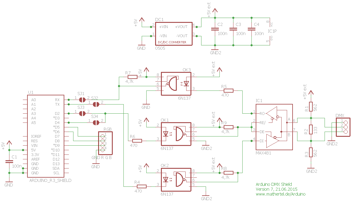
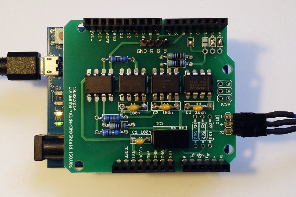
I’d also planned to design a opto and DC isolated interface, but came across the same author of the DMX Serial arduino library,Matthias Hertel, has designed a board already: http://www.mathertel.de/Arduino/DMXShield.aspx So will probably get some pcbs made and order some parts.


I now have a robertsonics wave trigger board, and reading this tutorial: http://robertsonics.com/2015/04/25/arduino-serial-control-tutorial/

That worked almost first go, I had to download an older version of the code- Apr 26, 2015 commit – due to comms issues in Sept 2016 version


Serial protocol for wavTrigger:

http://robertsonics.com/wav-trigger-online-user-guide/#chapter9

test code. havent tested with dmx input .. yet!

https://github.com/dargs/dargstronixDMXwavTrig


 if (lastPacket < 5000) { // if DMX received
 for (int x = 0; x < 20; x++){ // checking dmx channels 0 to 20. To Do: add dmx start address in future versions.
 
 if (DMXSerial.read(x) >= 0 && DMXSerial.read(x) <= 10 ) wTrig.trackStop(x); // Stop Track if DMX Value is between 0-10
 if (DMXSerial.read(x) >=11 && DMXSerial.read(x) <= 20 ) wTrig.trackPause(x); // Pause Track if DMX Value is between 11-20
 if (DMXSerial.read(x) >=21 && DMXSerial.read(x) <= 30 ) wTrig.trackResume(x); // Resume Track if DMX Value is between 21-30
 if (DMXSerial.read(x) >=31 && DMXSerial.read(x) <= 40 ) wTrig.trackPlayPoly(x); // Play Track if DMX value 31-40
 if (DMXSerial.read(x) >=41 && DMXSerial.read(x) <= 255 ) // Volume
 {
 signed int tempLevel = DMXSerial.read(x);
 signed int Level = map(tempLevel,21,255,-70,10);
 wTrig.trackFade(x, Level, 10, 0); // where (a,b,c,d) = a= track #, b=Level, c= fade time in milliseconds, d=0=contine playing, 1=stop playing
 }


Posted in Arduino-Projects | Leave a comment

Getting started with the Gadget Factory Papilio DUO – FPGA dev board

Finally learning some FPGA geeky goodness!

Back in 2014, I supported this campaign – https://www.kickstarter.com/projects/13588168/papilio-duo-drag-and-drop-fpga-circuit-lab-for-mak

And received the board 12 months ago, but haven’t had a play with it until now…

First things first..  check for a missing jumper, mentioned in update #23..

Install softwares.. I’m trying to install Designlab under windows 10, on my 2015 Macbook pro running Parallels


Downloaded ‘Papilio DesignLab IDE 1.0.7

http://forum.gadgetfactory.net/index.php?/files/file/236-papilio-designlab-ide/

Was able to get the hello world sketch running first time, blinking led and output to serial! Yay. Next to try out something using the computing shield…


Posted in Arduino-Projects, Uncategorized | Tagged | Leave a comment